WhatsApp
+62818-0847-5888
Work Hours
Monday to Friday: 9AM - 5PM
WhatsApp
+62818-0847-5888
Work Hours
Monday to Friday: 9AM - 5PM

Published by Sebatek | PT. Sebatek Prima Tunggal Industrial Lifting Equipment & Rigging Specialist
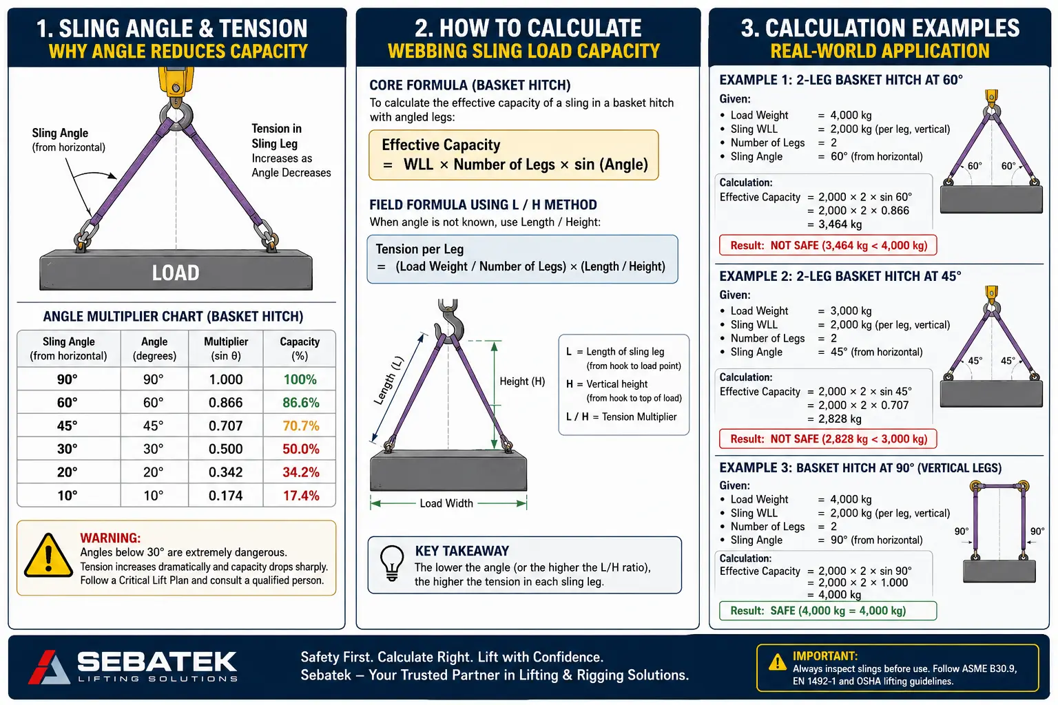
Calculating webbing sling load capacity requires three core inputs: the sling’s Working Load Limit (WLL), the number of sling legs, and the sling angle relative to horizontal. The fundamental formula is:
Effective Capacity = WLL × Number of Legs × sin(angle)
A 60° sling angle reduces effective capacity to 86.6% of rated WLL. At 30°, you lose half the capacity entirely. Safety factors under ASME B30.9 and EN 1492-1 require a minimum 5:1 ratio between Minimum Breaking Strength (MBS) and WLL. Always inspect before lifting, never exceed WLL, and account for dynamic loading and center of gravity before any lift begins.
Most lifting accidents don’t happen because riggers are careless. They happen because someone assumed the sling was strong enough without actually running the numbers.
A 2-tonne webbing sling in a basket hitch at 30° does not lift 4 tonnes safely. It lifts approximately 2 tonnes, the same as a single vertical hitch because the shallow angle cancels out the mechanical advantage you expected. That miscalculation has put workers in hospitals and pieces of machinery on the floor of facilities across Southeast Asia.
This guide exists to prevent that. It is not a marketing document. It is a working reference for procurement managers, safety officers, riggers, and engineers who need accurate, field-applicable knowledge on how to calculate webbing sling load capacity before committing to a lift.
Every formula, table, and principle here is grounded in ASME B30.9, EN 1492-1, and established OSHA lifting guidelines.
Before any calculation makes sense, the terminology has to be precise. These are not interchangeable terms.
WLL is the maximum load a sling is rated to handle under normal, controlled lifting conditions. It is the number printed on the sling tag. This figure already incorporates the design safety factor, it is not the breaking point, it is the operational ceiling.
MBS is the actual load at which the sling, under controlled laboratory testing, is expected to fail. It is always significantly higher than WLL because the safety factor sits between them.
Think of MBS as the cliff edge. WLL is where you stop well before the edge.
The safety factor is the ratio between MBS and WLL:
Safety Factor = MBS / WLL
Under ASME B30.9, the required safety factor for webbing slings is 5:1. This means a sling with a WLL of 1,000 kg must have an MBS of at least 5,000 kg.
Under EN 1492-1 (the European standard widely referenced in industrial markets across Asia), the minimum safety factor is also 7:1 for certain applications particularly where dynamic loads, shock loading, or critical lifts are involved.
Practical implication: If a sling’s tag shows a WLL of 2,000 kg and the standard requires a 5:1 safety factor, the sling must be rated to break at no less than 10,000 kg. If a sling does not carry a legible, permanently affixed tag with WLL information, it must be removed from service immediately per ASME B30.9 Section 9-1.7.
The hitch type fundamentally changes how load is distributed across the sling and what WLL applies.
The sling connects directly from the hook to the load attachment point in a straight line. One sling carries the full load.
This is the baseline configuration from which all other hitch calculations derive.
The sling passes under the load with both ends connected to the hook. The load sits in the center of the sling like a basket.
A basket hitch only achieves its 2x capacity when the legs hang perfectly vertical, which almost never happens in real lifting conditions. The moment the load is wider than the hook, the legs angle outward and the effective capacity drops. This is where most calculation errors occur.
The sling wraps around the load and passes through its own eye (or around a hook with the eye cinching tight). This creates a choking grip.
Warning: A choked sling that does not cinch squarely against the load creates a bent, concentrated load path. This accelerates wear and can cause failure well below the stated WLL.
This is the most important concept in webbing sling load capacity calculation, and the one most frequently misunderstood in the field.
When a sling is used in a basket hitch and the load is wide, the legs of the sling angle outward from the hook. The wider the load relative to the hook height, the shallower the angle and the more tension is required in each sling leg to support the same vertical load.
The vertical load a sling leg supports is only the vertical component of its tension. As the angle decreases from vertical, the horizontal component increases but horizontal tension does nothing to lift the load. It only stresses the sling.
This is a fundamental vector mechanics problem. The actual tension in each sling leg is:
Tension per Leg = (Load Weight / Number of Legs) × (Leg Length / Vertical Height)
Or equivalently, using trigonometry:
Tension per Leg = (Load Weight / Number of Legs) / sin(angle)
Where angle is measured from horizontal to the sling leg.
This table shows the reduction in effective WLL as sling angle decreases. These multipliers are derived directly from trigonometric sine values and are consistent with ASME B30.9 and EN 1492-1 guidance.
| Sling Angle (from horizontal) | Angle Multiplier | Capacity Retained |
|---|---|---|
| 90° (vertical) | 1.000 | 100% |
| 60° | 0.866 | 86.6% |
| 45° | 0.707 | 70.7% |
| 30° | 0.500 | 50.0% |
Critical Note: ASME B30.9 and most rigging standards prohibit sling angles below 30° from horizontal. Below 30°, sling tension increases so dramatically that even a momentary overload can cause catastrophic failure. Many competent persons adopt a practical minimum of 45° on-site.
A 2-tonne WLL sling in a two-leg basket hitch:
The load hasn’t changed. The sling hasn’t changed. Only the angle changed — and you lost half your lifting capacity.
Effective Capacity = WLL × Number of Legs × sin(angle)
Where:
When you know the total load and need to verify that each leg is within WLL:
Tension per Leg = (Load Weight / Number of Legs) × (Leg Length / Vertical Height)
This formula is particularly useful in the field when you can measure sling length and vertical height directly but cannot easily measure the angle with a protractor.
Scenario: Lifting a steel fabrication weighing 3,200 kg using a two-leg sling bridle. The sling legs are 2 meters long. The lift point is 1.73 meters above the load attachment points, giving a 60° angle from horizontal.
Step 1: Identify the load weight Total load = 3,200 kg
Step 2: Determine the angle multiplier Angle = 60°, multiplier = 0.866
Step 3: Calculate the tension per leg
Tension per Leg = (3,200 / 2) × (2.0 / 1.73)
               = 1,600 × 1.156
               = 1,850 kg per leg
Step 4: Select sling WLL Each sling leg must have a WLL of at least 1,850 kg. Select 2,000 kg WLL slings.
Step 5: Verify effective capacity
Effective Capacity = 2,000 × 2 × 0.866 = 3,464 kg
3,464 kg > 3,200 kg. The selected slings are adequate.
Scenario: Lifting a horizontal structural beam weighing 6,000 kg with a four-leg sling arrangement. Legs are angled at 45°.
Tension per Leg:
Tension per Leg = (6,000 / 4) / sin(45°)
               = 1,500 / 0.707
               = 2,122 kg per leg
Each sling leg requires a WLL of at least 2,122 kg. Select 2,500 kg WLL slings.
Effective Capacity check:
Effective Capacity = 2,500 × 4 × 0.707 = 7,070 kg
7,070 kg > 6,000 kg. Adequate with approximately 18% margin.
Note on four-leg slings: ASME B30.9 states that when calculating a four-leg sling, it is conservative practice to assume only three legs share the load equally, because perfect load distribution across all four legs simultaneously is difficult to guarantee in field conditions. For critical lifts, design accordingly.
Static WLL calculations assume the load is lifted smoothly, held steadily, and lowered in a controlled manner. Real lifts rarely follow this ideal.
Dynamic loading occurs when:
Dynamic loading multiplies the effective weight the sling must carry. The dynamic load factor can range from 1.1 (smooth controlled lift) to 2.0 or higher (snatch pick from stuck position or freefall arrest).
For standard industrial lifts: Apply a minimum dynamic factor of 1.3 when the load weight calculation does not already include this margin.
Design Load = Static Load Weight × Dynamic Load Factor
For the 3,200 kg example above:
Design Load = 3,200 × 1.3 = 4,160 kg
The sling selection must be based on 4,160 kg, not 3,200 kg.
A load’s center of gravity (CoG) determines how it hangs. If the CoG is not directly below the crane hook, the load will tilt during the lift.
An off-center CoG has two consequences:
For a two-point lift where the CoG is off-center:
If CoG is located at distance ‘a’ from one attachment point and distance ‘b’ from the other, and total span is (a + b):
Load on near leg = Total Weight × (b / (a + b))
Load on far leg  = Total Weight × (a / (a + b))
The sling on the near leg (closer to CoG) carries the larger share. Design that leg for the full calculated load.
Field Rule: If a load doesn’t hang level during a test lift, do not proceed. Re-rig to adjust the CoG balance before completing the lift. Tilting loads are unpredictable and their effective sling loads change dynamically.
Even in a balanced lift, not all sling legs carry exactly equal loads. Variations in:
…all cause unequal load sharing. This is why conservative calculation practice often designs for 3 legs carrying the load even when 4 are used.
For critical lifts, use a spreader beam to force parallel leg geometry, which dramatically improves load distribution predictability and allows higher effective capacity utilization.
The American Society of Mechanical Engineers B30.9 standard is the primary reference for slings used in lifting service in North America, and is widely adopted as a baseline in industrial facilities globally. Key requirements include:
The European standard EN 1492-1 covers flat woven webbing slings. It requires:
OSHA 1910.184 and 1926.251 govern sling use in general industry and construction respectively. Key practical requirements:
This section is non-negotiable. Any of the following conditions requires immediate removal from service:
Before any lift using webbing slings, verify the following:
Warning: Common Mistakes That Cause Sling Failures
Ignoring the angle: A sling selected based on its vertical WLL but used at 30° has only 50% of the expected capacity. This is the most common calculation error.
Misidentifying WLL by hitch type: A 3-tonne WLL rating marked on a sling typically refers to the vertical hitch. In a choker hitch, the same sling is only rated to 2.25 tonnes (0.75 × 3t). Always confirm which hitch configuration the tag rating refers to.
Using color as the only identifier: EN 1492-1 color coding is useful for quick identification but must be confirmed against the physical tag. Faded or contaminated slings may not display their original color accurately.
Forgetting dynamic loading in shock pick scenarios: Pulling a load free from a stuck or partially buried position can generate instantaneous forces 3x to 5x the static load weight. Never use a crane and webbing slings to break free a stuck load.
Using knots to shorten a sling: Knotting synthetic webbing reduces rated capacity by up to 50% and creates permanent damage at the knot site. Use hardware adjusters or a sling of the correct length.
WLL (Working Load Limit) is the maximum load the sling is certified to carry in normal lifting conditions. It is calculated by dividing the Minimum Breaking Strength by the safety factor (5:1 under ASME B30.9 or 7:1 under EN 1492-1). It is specific to both the sling itself and the hitch configuration being used.
Sling angle is the angle between the sling leg and a horizontal plane. As the angle decreases, more tension is required in each sling leg to support the same vertical load. At 30° from horizontal, each sling leg carries twice the tension compared to a vertical hitch, effectively reducing the capacity to 50% of rated WLL.
ASME B30.9 does not technically permit a minimum angle below 30° from horizontal. However, most experienced rigging engineers set a practical minimum of 45° on-site to maintain adequate safety margin and avoid unexpected overload from load swing or dynamic effects.
The safety factor defines how many times the WLL you can go before reaching the theoretical breaking point. A 5:1 safety factor (ASME B30.9) means the sling must break at 5 times its WLL. A 7:1 safety factor (EN 1492-1) means 7 times WLL a higher degree of built-in reserve. Use the higher standard for critical lifts, high-cycle operations, or applications with significant dynamic loading.
Per ASME B30.9 and OSHA 1910.184: before each lift (visual inspection by the user), and formally at intervals determined by a competent person based on frequency of use, severity of service conditions, and the sling’s service history. High-frequency industrial slings should be formally inspected and documented at least quarterly. Any sling showing rejection criteria conditions must be withdrawn immediately regardless of when it was last inspected.
Not without corner protection. Sharp edges cut webbing fibers under load, often catastrophically and without visual warning. Use corner pads, pipe protectors, or edge guards rated for the contact load. The corner protection must be secured so it cannot shift during the lift.
Not in practice. While four legs theoretically provide 4x capacity at 90°, ASME B30.9 cautions that due to load distribution uncertainty in real field conditions, a four-leg sling should be treated as a three-leg sling for design purposes. Spreader beams, when used, improve distribution and may allow more of the fourth leg’s capacity to be utilized.
EN 1492-1 color codes webbing slings by WLL: Violet (1t), Green (2t), Yellow (3t), Grey (4t), Red (5t), Brown (6t), Blue (8t), Orange (10t). These color codes apply to the body of the sling and the label. Always confirm against the physical tag, as colors can fade or become contaminated in service.
| Parameter | What It Means | Where It Comes From |
|---|---|---|
| WLL | Maximum operational load | Sling tag / manufacturer certification |
| MBS | Actual break load | Factory test data |
| Safety Factor | MBS / WLL | ASME (5:1) or EN (7:1) |
| Angle Multiplier | sin(angle from horizontal) | Trigonometry / rigging tables |
| Dynamic Factor | Multiplier for real-world forces | Engineering judgment (min 1.3) |
| Design Load per Leg | What each leg actually carries | Calculation (see formulas above) |
The fundamental rule: Design Load per Leg must never exceed the WLL of the sling in the chosen hitch configuration, after all multipliers and factors have been applied.
Sebatek by PT. Sebatek Prima Tunggal supplies industrial lifting equipment and rigging solutions to facility operators, EPC contractors, and maintenance teams across Indonesia. The product range covers webbing slings across all standard WLL classes from 1 tonne through 10 tonnes, certified to EN 1492-1, with full documentation and traceable batch certifications.
What differentiates a reliable lifting equipment supplier is not just the product — it is the ability to help you select the right configuration for your specific application. Sling selection that appears straightforward on paper can become complex in the field when load geometry, available headroom, attachment hardware, and load surface conditions all interact.
If you are planning a lift and are unsure whether your current sling inventory is correctly sized, or if you need slings for a specific project with documented load calculations, the Sebatek team can assist with:
There is no cost to a consultation conversation. Getting the sling selection right costs far less than an incident investigation.
Contact Sebatek for lifting equipment consultation and certified sling supply: reach out directly to the Sebatek industrial team for technical support on your lifting requirements by Chat here
This guide references ASME B30.9 (Slings), EN 1492-1 (Flat Woven Webbing Slings), and OSHA 1910.184 / 1926.251. All formulas and multipliers are consistent with current edition standards. This document is intended as an engineering reference and does not substitute for site-specific risk assessment, lift planning by a competent person, or compliance with applicable local regulations.
Sebatek | PT. Sebatek Prima Tunggal Industrial Lifting Equipment | Rigging Solutions | Safety-First Supply
